


Model:T12
Weigand 26 out/in (be used as weigand reader to controller,connect extra reader )
EM/ID or Mifare/IC Reader Built in
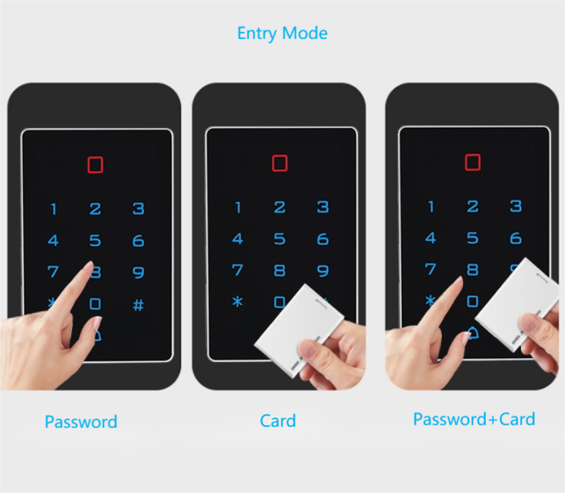
Entry Mode:Card/Card+Pin/Pin
Operating Voltage:12-24 V DC <30mA
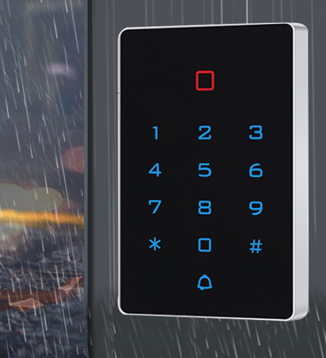
Optional Functions: Wifi Tuya APP/ Waterproof IP68
Description
Tuya APP WIFI Access Controller EM 125Khz / IC 13.56mhz Card Reader
1.Wifi Access Controller Description
The device is a standalone access control and proximity card reader which supports EM & MF card types. It builds-in STC microprocessor, with strong anti-interference ability,high security and reliability,powerful function and convenient operation. It’s widely used in high-end buildings, residential communities and other public places.

2. Wifi Access Controller Features
| Ultra-low Power | Power Standby current is less than 30mA |
| Wiegand Interface | WG26 Input and output |
| Searching time | Less than 0.1s after reading card |
| Backlight keypad | Operate easily at night |
| Doorbell interface | Support external wired doorbell |
| Access ways | Card, Pin code, Card & Pin code |
| Independent codes | Use codes without related card |
| Change codes | Users can change codes by themselves |
| Delete users by card No. | The lost card can be delete by keyboard |
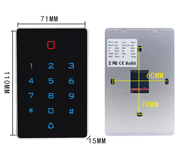
2. Wifi Access Controller Specifications
| Working Voltage:DC12-24V | Standby Current:≤30mA |
| Card Reading Distance:1~3cm | Capacity:2000 users or pin |
| Working Temperature:-40℃~ 60℃ | Working Humidity:10%~90% |
| Lock output load:≤3A | Door Relay time:0~99S (Adjustable) |
| Frequency: EM 125khz / IC 13.56mhz | Waterproof: IP68 ( optional ) |
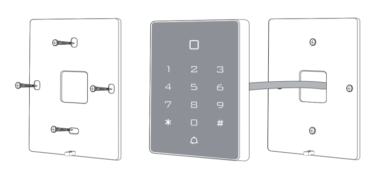
3. Wifi Access Controller Installation
Drill hole according to the size of the device and fix the back shell with the equipped screw.
Thread the cable through the cable hole. connect the wires according to your required function, and wrap the unused wires to avoid short circuit. After connecting the wire, install the machine. (as show below)
4. Wifi Access Controller Diagram
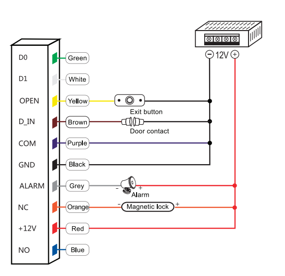
4.1 Common Power Supply
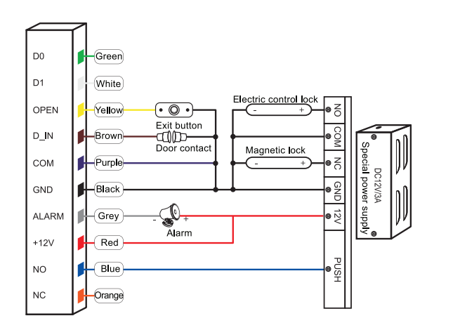
4.2 Special Power Supply
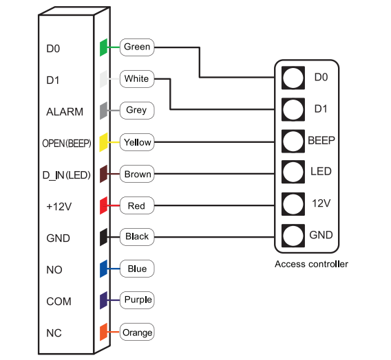
4.3 Reader Mode
5.Data Backup Operation
Example: Backup the data of machine A to machine B
The green wire and white wire of machine A connects with the green wire and white wire of machine B
correspondingly, set B for receiving mode at first, then set A for sending mode, the indicator light turns green
flash during the data backup, data backup is successful when indicator light turns red.
![]()


